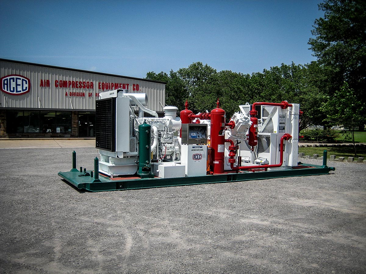
Typical boosters used in oil-field applications are, as the name implies, designed to boost incoming compressed air, nitrogen, or natural gas to a higher discharge pressure.
Boosters come in a number of combinations regarding cylinder size and number of stages depending on the flow of compressed gas and the discharge pressure required.
When discussing high discharge temperatures it’s important to note that this could mean high discharge temperatures for any of the stages of compression. If we are talking about a two-stage booster, high discharge temperatures could result in the first or second stage of compression. A four-stage booster would have four discharge points where high temperatures could exist. Multiple stages of compression are used so that the compressed gas can be cooled before moving onto the next stage.
Most of the boosters that we build are two-stage boosters in two different size categories.
Our large boosters used in air drilling applications have a 6-inch first stage cylinder and a 4.25-inch second stage cylinder. The smaller boosters used in well-stimulation applications, and usually mounted on a trailer with a compressor and mist pump to create an air foam unit, will have a 3.875-inch first stage cylinder and a 2.75-inch second stage cylinder. The only difference in these two boosters is the amount of gas volume they can move. The larger cylinders will move more volume than the smaller cylinders. Each of the above boosters, regardless of size, will have safety shutdowns for the discharge temperature of each cylinder. The shutdown temperatures will be set at 350˚F.
The possible causes of high booster discharge temperatures for any stage could be the following:
- Excessive compression ratio across the cylinder
- Leaking inlet or discharge valves
- Fouled intercooler piping
- High inlet gas temperature
- Improper lube oil and or lube rate
Excessive Compression Ratio
The max compression ratio per stage for air compression is 2.5 times. This means that if we have a suction pressure of 400PSIG on the first stage of compression, we can increase the pressure to 1,000PSIG before we start to run into temperature problems. After the first stage of compression, the air would move though a cooler before moving on to the second stage of compression. The second stage would take that 1,000PSIG and be able to increase it to 2,500PSIG for the final discharge. Flows will not change, but there are atmospheric conditions that will affect the max compression ratios resulting so use the 2.5 times as a general rule of thumb.
Leaking Suction or Discharge Valves
Faulty valves that aren’t opening and/or closing normally will affect the amount of volume a booster can move and the discharge temperatures of the cylinders. Valves can also have a bad seat where the valves sit into the valve pockets. Either of these conditions will cause the booster to operate at higher than normal discharge temperatures. The gas being compressed will stack up in either cylinder affecting the overall volume of compressed gas moving through the system. If the gas isn’t moving through the system, temperatures will increase as the hot gas gets recompressed instead of being sent into the cooler group. An important side note is that faulty valves in one cylinder can affect temperatures in any other cylinder. If suction valves aren’t working on the high side, gas will stack up in the low side cylinder resulting in higher than normal discharge temperatures for the low side.
Fouled Intercooler Piping
Fouled intercooler piping means that the internal piping of the cooler group is plugged up due to varnish or trash in the system or it can mean that the space around the cooler tubes is plugged with dirt, oil, and debris causing a loss of flow across the cooler tubes. With a plugged intercooler, gas flow would be restricted and gas would stay in the low side cylinder too long causing high temperature issues in the low side cylinder. If the cooler core is plugged with dirt, oil, and debris, the cooler cannot get sufficient air flow across the cooler tubes, which decreases the amount of heat rejection of the gas. This would result in high suction/discharge temperatures for the high side cylinder.
High Inlet Gas Temperature
The max suction temperature that a booster can handle and still operate without shutting down on high discharge temperature would be somewhere in the 120-130˚F range. Discharge temperatures are a function of the temperature of the gas on the suction side of the cylinder, the ambient temperatures, the compression ratio from suction to discharge, the dew point of the gas, ect.. Point is, if the suction temperature of the gas is elevated, all other variables have to be lowered or discharge temperatures will become elevated to the point of shutdown.
If a booster is shutting down on high discharge temperature, one of the first things to check is the suction temperature of the gas. If it’s an air foam unit compressing air, the high temperature on the suction side of the booster is most likely coming from a faulty cooler on the compressor feeding the booster. Suction temperatures should not exceed a 20˚F approach – this means that the suction temperature of the gas being compressed shouldn’t be more than 20˚F higher than the ambient condition. If the ambient temperature is 100˚F then the suction temperature should not exceed 120˚F.
Improper Lube Oil or Lube Rate
The internal components of a booster are similar to a car engine. There are pistons that ride on piston rings inside of cylinder walls. Running at 1800RPM all day long requires lubrication to keep the internal parts from burning up from frictional heat. Lubrication is used to ease the friction.
Two things are very important regarding booster lubrication: 1) the viscosity of the lubrication and 2) the lube rate of the booster frame. The viscosity of booster fluids is higher than that of rotary screw compressors and should be in the ISO VG 100-150 range. Using a lubricant with too low of a viscosity will cause premature wear and, at some point, metal-on-metal friction causing excessive heat and shutdown conditions on the discharge side of the booster cylinder.
The lube rate should be specific to the booster and can usually be found on the nameplate on the booster frame itself. A ProFlo lube rate counter/shutdown device should be used so the operator can see instantaneous and average lube rates for the booster and how those figures compare to the nameplate data. Lube rates can be adjusted at the primer pump.

